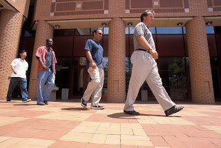
Wednesday, December 9, 2009

Activity 3: Silhouette Extraction

Did you know that your gait or the way you walk, like your fingerprint, is unique to every individual? What's more interesting is that it can also be analyzed through pattern recognition techniques. In fact, studies conducted on individuals' unique manner of walking, paved the way for experiments on silhouette extraction.

Figure 1. Gait


The study on the gait processing of an individual was initiated in the field of medicine to examine the walking patterns of impaired patients [1,2]. A decade after, it was first used as a pattern recognition technique by Johansson when he used reflectors affixed to the joints of a human body and showed motion sequences as the person walks[3]. The observers were able to identify gender and in some cases person recognition was obtained. Previous works on the use of gait for person identification have mostly utilized side-view gait (pendulum analogy) for feature extraction because temporal variations are more obvious from the side than the front. In this activity, we show and test the biometric feature developed by Soriano et al. that uses the idea of silhouette extraction, the freeman vector code and vector gradients to characterize the concavities and convexities in an image[4].


Experiment

Our first task was to capture an object against a steady background. In one of our conversations in class, Dr. Soriano suggested to use my mouth as the object mainly because she was curious if silhouette extraction can be applied to investigate the relationship between the opening of the mouth and the words (or sound) produced. If we are able to establish the said technique, then it could be a big help in the communication industry since communications with the use of web cameras nowadays is becoming widespread.

We then got the edge of the object of interest using edge detection algorithms and made sure that the edges were one-pixel thick. This is very important as problems may arise in the reconstruction of the curve spreads when the edges are more than a pixel thick. In fact, I encountered problems in the early part of the activity mainly because of the large size of my image and the edges, which were thicker than a pixel. To find the x-y coordinates of the edge, we used the regionprops and pixellist in Matlab.

Figure 2. Sample mouth image (image size: 170 x 122)


Figure 3. Image after applying the edge detection algorithms which include: (a). im2bw (b) edge and bwmorph and imfill.


Note that all the neighboring pixels of an edge pixel can be represented by one number only (from 1 to 8) in the Freeman vector code as shown in Figure 4. We then replaced the edge pixel coordinates with their Freeman Vector Code, took the difference between the codes of two adjacent pixels and performed a running sum of three adjacent gradients. The vector gradient details include: concavity (negative values), convexity (positive numbers bounded by zeros) details and straight line (zeros).


Figure 4. Freeman Vector Code illustration.


Figure 5. The pixel edges of the image with corresponding Freeman Vector code. Inset shows the whole Freeman vector code for the mouth image.


Figure 6. Processed image with corresponding values for the vector gradients. Inset shows the vector gradients for the mouth image.


Figure 6 shows the chain of zeros, positive and negative numbers placed in their appropriate pixel coordinates where zeros are regions of straight lines, negatives are regions of concavities and positives are regions of convexities.


Tips:

One of the more challenging steps in this activity is obtaining an image which is one-pixel thick after edge detection. Before my mouth, which was a success, I tried taking a picture of a hat, a watch and even my pen to no avail.


Since we were able to accurately reconstruct the different regions in the image, this activity may jumpstart the research in identifying the relationship between the shape of the mouth opening and the sound produced. I give myself a grade of 10 in this activity since I was able to reconstruct the regions of straight lines(zeros), concavities(negatives) and convexities(positives) placed in the appropriate pixel coordinates.


References:

[1] Murray, M.P., Drought, A.B., Kory, R.C. 1964. Walking Patterns of normal men. J. Bone Joint Surg. 46-A (2), 335-360.

[2] Murray, M.P 1967. Gait as a total pattern movement. Am. J. Phys. Med. 46(1), 290-232

[3] Johansson G., 1975. Visual Motion Perception. Sci. Am. 232, 76-88.

[4] Soriano, M., Araullo, S. and Saloma, C. 2004. Curve Spreads – A biometric from front-view gait video, Pattern Recognition Letters, 25, 1595-1602.


For teaching concerns please visit: https://sites.google.com/site/alongjas/

Activity 2: Hough Transform

I. Theory

The Hough Transform was patented by--surprise!--Paul Hough in 1960. The classic Hough transform was concerned with the identification of the lines in an image. It was later developed and popularized, two decades after, with its application to any arbitrary shape like circles and ellipses. It is now widely used in a variety of related methods for shape detection since it is tolerant of gaps in feature boundary descriptions and is relatively unaffected by image noise. This feature extraction technique is used in a wide range of fields including computer vision, image analysis and digital image processing.


II. Experiment

We were tasked to capture a gray scale image of a scene with straight lines. The image I chose was that of a lion inside a steel cage taken in the Baluarte mansion of then Ilocos Sur governor Chavit Singson. I had to first binarize the image (convert into its black and white version) and did edge detection before proceeding with the Hough transform technique. A successful implementation of this technique will result in an image with lines properly superimposed on straight edges in the image.


Figure 1. Image of a lion inside a cage taken in Balaurte, Ilocos Sur (image size: 450 x 600).


Figure 2. Black and white version of the sample lion image using the im2bw command in Matlab.
Figure 3. The edges in the lion image using the edge detection algorithm available in Matlab.


The Hough transform is designed to detect lines using the parametric representation of a line:

rho = x * cos(theta) + y * sin(theta) (1)

Rho is the distance from the origin to the line along a vector perpendicular to the line and theta is the angle between the x-axis and this vector.

We then used Hough Transform function in Matlab to create an accumulator matrix based on the parameters r and θ. Then we found the peaks in the accumulator matrix and converted the r and θ values into the equation of a line.
Figure 4. Computed Hough Transform of our image in 'hot' color map version with the peaks represented by the small squares

Figure 5. Superimposed lines on the original image indentified using the Hough Transform.


Figure 5 shows the superimposed lines on the cage, in the original image identified by the Hough Transform technique. The blue line represents the longest identified straight edge while the green lines represent the other straight edges. Comparing Figures 1 and 5, we notice that the Hough transform reconstructed the thin straight edges and those that easily blend with the background(faint ones).


Tips:

1. The hough function in Matlab easily generates a parameter space matrix whose rows and columns correspond to the rho and theta values respectively.

2. After computing for the Hough transform, use the houghpeaks function to find the peak values in the parameter space. The peaks represent potential lines in the input image

3. Use houghlines to find the endpoints of the line segments corresponding to the peaks in the Hough transform. The function automatically fills in gaps in the line segments.


We were successful in
identifying the straight edges in our cage image by using the classic Hough transform. I give myself a grade of 10 in this activity. This activity is much easier than the first one, adaptive segmentation and tracking using the color locus, mainly because the functions needed are readily available in Matlab.


References:

[1] http://www.cogs.susx.ac.uk/users/davidy/teachvision/vision4.html
[2] Maricor Soriano, Applied Physics Lectures: Hough transform. 2009
[3] MATLAB R2008a

For teaching concerns please visit: https://sites.google.com/site/alongjas/

Activity 1: Adaptive Color Tracking

When we are asked to describe a person physically, one of the characteristics that we often notice or remember is the color of the person's skin. Indeed, skin color is one of the main traits that is being sought after in pattern recognition techniques. Usual techniques that employ color-based tracking uses a static skin model. But the problem is, based from our daily experience, we easily notice that the skin color changes as illumination conditions vary. In this activity, we reproduce an adaptive color-tracking technique that was developed by Soriano et. al. that utilizes a chromaticity based constraint to select training pixels in a scene for updating a dynamic skin color model. The technique is successfully applied to color-based face tracking in indoor and outdoor videos.


Figure 1. Varying skin color across different races.


Experiment

I used a captured video of a labmate, Kirby Cheng, a 3rd year BS Applied Physics student, under various illuminations inside the Instrumentation Physics Laboratory and at the NIP corridor as shown in the figure below.


Figure 2. Images of Kirby under different illuminations: (a) - (b) with yellow lighting inside the Instrumentation Physics laboratory, (c) - (d) daylight at the National Institute of Physics (NIP) corridor and outside the NIP.


The Kirby video was first parsed into image frames. From one image frame, we cropped a sub-image of the region of interest (ROI), i.e. his skin, and computed its rg-histogram. The procedure was then repeated for frames where there were drastic changes in skin color. We estimated the color locus of that object using the computed rg-histograms and we performed histogram backprojection per frame.


Figure 3. Image overlayed with the corresponding bounding box


As seen in Figure 3, the size of the bounding box varies under varying illumination. Note that a larger bounding box is observed for the images with yellow lighting given that the color of Kirby's skin blends with the surrounding, thanks to his Chinese genes, while a relatively smaller bounding box appears for the daylight illumination. The image frames exhibit an unbroken tracking of Kirby’s skin under different illuminations.


Tips:


1. Make sure to first convert the rgb images to black and white using the im2bw command in Matlab.


2. Apply morphological operations to binarize the image and remove non-ROI blobs.


3. Use bwlabel to label the index blobs and regionprops to find blob features.


4. To speed up processing for real-time applications, confine object segmentation in the next frame within a slightly larger bounding box than the blob bounding box.


I give myself a grade of 10 for this activity since I was able to satisfy the main objective, which is to track the skin color of the sample under varying illuminations. As a side note, I spent a greater time on this activity mainly because I needed more time in reviewing the syntax and commands available in Matlab.


Reference:

[1]M. Soriano, B. Martinkauppib, S. Huovinenb and M. Laaksonenc, "Adaptive skin color modeling using the skin locus for selecting training pixels"
Pattern Recognition 36 (2003) 681 – 690

For teaching concerns please visit: https://sites.google.com/site/alongjas/